Guidelines for Operator Facility Field Delineation
BEST PRACTICES CHAPTER 4 - LOCATING AND MARKING
Practice Statement 4-3:
Color Code: A uniform color code and set of marking symbols is adopted nation wide.
Operator markings of facilities include the following:9
- The appropriate color for their facility type
- Their company identifier (name, initials, or abbreviation) when other companies are using the same color
- The total number of facilities and the width of each facility
- A description of the facility (HP, FO, STL, etc).
Use paint, flags, stakes, whiskers, or a combination to identify the operator’s facility(s) at or near an excavation site.
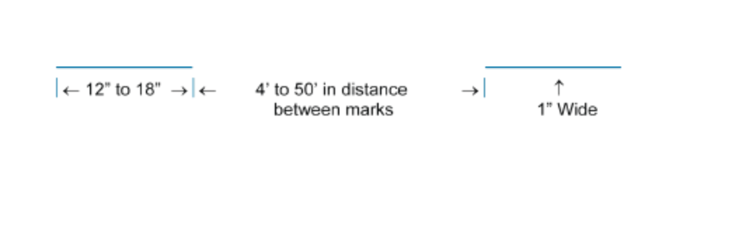
1. Marks in the appropriate color are approximately 12 in. to 18 in.long and 1 in. wide, spaced approximately 4 ft to 50 ft apart. When marking facilities, the operator considers the type of facility being located, the terrain of the land, the type of excavation being done, and the method required to adequately mark the facilities for the excavator.
2. The following marking examples illustrate how an operator may choose to mark their subsurface installations:
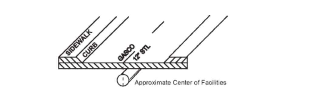
a. Single Facility Marking: Used to mark a single facility. This can be done in one of two ways—
1) placing the marks over the approximate center of the facility:
2) placing the marks over the approximate outside edges of the facility with a line connecting the two horizontal lines (in the form of an H) to indicate there is only one facility:
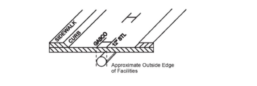
These examples indicate an operator’s 12 in. facility. When a facility can be located or toned separately from other facilities of the same type, it is marked as a single facility.41
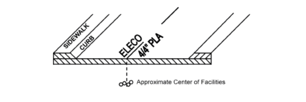
b. Multiple Facility Marking: Used to mark multiple facilities of the same type (e.g., electric), where the separation does not allow for a separate tone for each facility, but the number and width of the facilities is known. Marks are placed over the approximate center of the facilities and indicate the number and width of the facilities.
Example: four plastic facilities that are 4 in. in diameter (4/4" PLA)
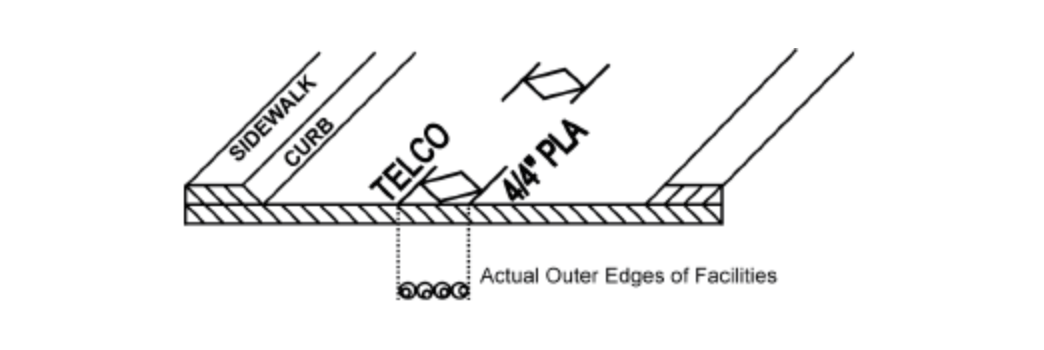
c. Conduit Marking: Used for any locatable facility being carried inside conduits or ducts. The marks indicating the outer extremities denote the actual located edges of the facilities being represented.
Example: four plastic conduits that are 4 in. in diameter (4/4" PLA), and the marks are 16 in. apart, indicating the actual left and right edges of the facilities
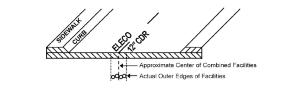
d. Corridor Marking: Used to mark multiple facilities of the same type (e.g., electric), bundled or intertwined in the same trench, where the total number of facilities is not readily known (operator has no record on file for the number of facilities). Marks are placed over the approximate center of the facilities and indicate the width of the corridor. The width of the corridor is the distance between the actual located outside edges of the combined facilities.
Example: a 12 in. corridor (12" CDR)
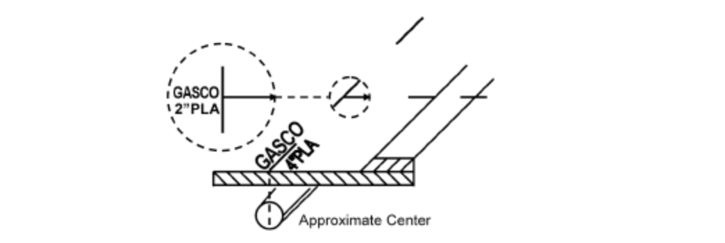
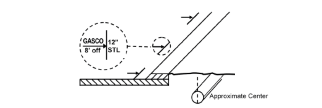
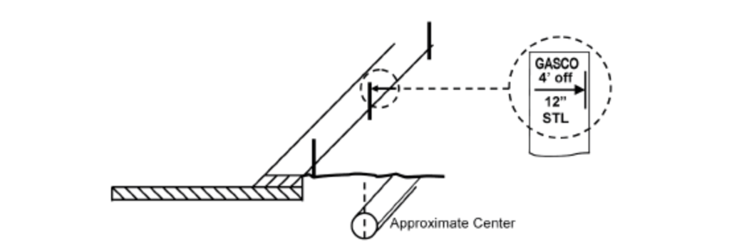
3. Changes in direction and lateral connections are clearly indicated at the point where the change in direction or connection occurs, with an arrow indicating the path of the facility. A radius is indicated with marks describing the arc. When providing offset markings (paint or stakes), show the direction of the facility and distance to the facility from the markings.
Example: radius

Example: lateral connection
Example: painted offset (off)
Example: staked offset (off)
4. An operator’s identifier (name, abbreviation, or initials) is placed at the beginning and at the end of the proposed work. In addition, subsequent operators using the same color mark their company identifier at all points where their facility crosses another operator’s facility using the same color. Reduce the separation of excavation marks to a length that can reasonably be seen by the operator’s locators when the terrain at an excavation site warrants. Examples:
Examples:

5. Information regarding the size and composition of the facility is marked at an appropriate frequency.
Examples: the number of ducts in a multi-duct structure, width of a pipeline, and whether it is steel, plastic, cable, etc.

6. Facilities installed in a casing are identified as such.
Examples: 6 in. plastic in 12 in. steel and fiber optic in 4 in. steel

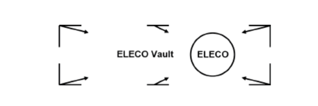
7. Structures such as vaults, inlets, and lift stations that are physically larger than obvious surface indications are marked so as to define the parameters of the structure.
Example:
8. Termination points or dead ends are indicated as such.
Example:

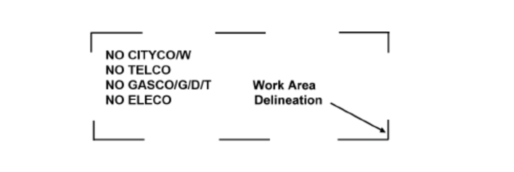
9. When there is “No Conflict” with the excavation, complete one or more of the following:
- Operators of a single type of facility (e.g., TELCO) mark the area “NO” followed by the appropriate company identifier in the matching APWA color code for that facility.
Example: NO TELCO
- Operators of multiple facilities mark the area “NO” followed by the appropriate company identifier in the matching APWA color code for that facility with a slash and the abbreviation for the type of facility for which there is “No Conflict.”
Example: NO GASCO/G/D illustrates that GASCO has no gas distribution facilities at this excavation site. The following abbreviations are used when appropriate: /G/D (gas distribution); /G/T (gas transmission); /E/D (electric distribution); /E/T (electric transmission).
- Place a clear plastic (translucent) flag that states “No Conflict” in lettering matching the APWA color code of the facility that is not in conflict. Include on the flag the operator’s identifier, phone number, a place to write the locate ticket number, and date. Operators of multiple facilities indicate on the flag which facilities are in “No Conflict” with the excavation (see the previous example).
- If it can be determined through maps or records that the proposed excavation is obviously not in conflict with their facility, the locator or operator of the facility may notify the excavator of “No Conflict” by phone, fax, or e-mail, or through the 811 center, where electronic positive response is used. Operators of multiple facilities indicate a “No Conflict” for each facility (see the previous examples).
- Place “No Conflict” markings or flags in a location that can be observed by the excavator and/or notify the excavator by phone, fax, or e-mail that there is “No Conflict” with your facilities. When the excavation is delineated by the use of white markings, place “No Conflict” markings or flags in or as near as practicable to the delineated area.
Caution: Allow adequate space for all facility mark-outs.
“No Conflict” indicates that the operator verifying the “No Conflict” has no facilities within the scope of the delineation; or when there is no delineation, there are no facilities within the work area as described on the locate ticket.
Example: